
As automotive designs become more electrified, high-wattage power electronics become increasingly important in new electronic drivetrain and battery systems. Thanks to galvanic isolation, digital controllers can safely interface with the high-voltage systems of modern electric vehicles in these applications.
Galvanic isolation is critical to the operation of these circuits, so it’s worth reviewing the fundamentals of power isolation and how it’s implemented in modern automotive electronics.
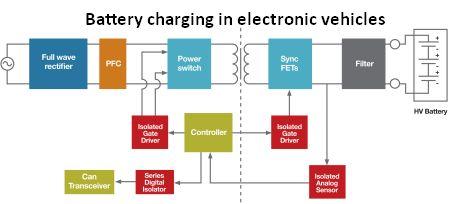
Block diagram of a typical on-board charger system, including galvanic isolation components.
Galvanic isolation is a technique for preventing current flow between two components of an electrical system. Galvanic isolation differs from ohmic isolation in that there is no direct conduction path between the two circuits. In other words, the output power circuit is electrically and physically separated from the input power circuit. However, galvanic isolation for the exchange of energy or information between the two sections via other means.
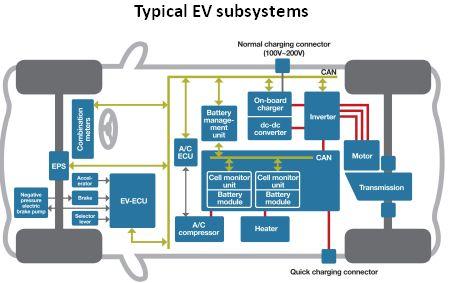
The standard subsystems that comprise an EV.
Galvanic isolation may be required for two reasons. The first is that the two electrical systems’ electrical grounds may be at different potentials. In the absence of galvanic isolation, ground loop current can flow between two units that share a ground conductor.
Ground-loop currents are electrical noise that can disrupt the operation of either circuit. Furthermore, if the difference in ground potentials is large enough, the resulting ground-loop current can be dangerous.
As a result, the second reason for galvanic isolation is operational safety. Galvanic isolation in automotive electronics is required for safety reasons. High-voltage circuitry carries lethal currents in EVs and mild hybrid electric vehicles (HEVs).
Digital electronics with milliamp-level currents control the high-voltage sections. Galvanic isolation is a more robust method of preventing faults in power stages from damaging the control electronics that operate them when compared to other types of isolation.
Circuits With High Voltage in Evs
Reviewing the high-power circuits found in EVs and HEVs is beneficial. Both types of vehicles use 48-volt systems and batteries that have a high energy storage density and can charge in minutes rather than hours.
Furthermore, the battery management and associated power conversion system must be small and lightweight, as well as capable of “sipping” battery current. The drive train and energy storage/conversion systems in modern EV/HEV designs are modular. The following major circuit assemblies are commonly found in EV/HEV battery management systems:
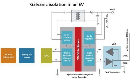
How solid-state galvanic isolation can be used in a battery management system’s communication interface. The battery pack is located on the high-voltage domain. The CAN transceiver is located on the low-voltage domain side. The CAN bus interface is highlighted in this example.
In most cases, additional power isolation between the microcontroller and the battery pack is included in real-world systems.
- On-board charger (OBC): A lithium-ion battery is charged by an onboard charger, which consists of an ac-to-dc converter with power factor correction and is monitored by a battery management system.
- Battery Management System (BMS): The BMS monitors and manages the charging and discharging of battery cells in order to ensure maximum efficiency and safety. The BMS, in particular, regulates the charging, health, depth of discharge, and conditioning of individual battery cells.
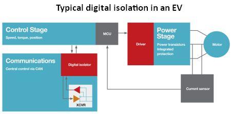
How different digital isolation devices might operate in a simplified traction motor control system.
- DC/DC Converter: The dc/dc converter connects the high-voltage battery to the internal 12-volt dc network, which also powers accessories and provides bias to the local switching converters.
- Main Inverter: The main inverter is responsible for driving the electric motor as well as regenerative braking and recharging the battery with unused energy.
High-performance isolation shields digital controllers on the vehicle from voltages that can exceed 300 volts. High-voltage subsystems, such as the OBC, are typically controlled over a CAN bus, which must also be isolated.
In an EV, low-voltage controllers communicate with high-voltage subsystems via connections that are frequently noisy due to proximity to high currents and electrical switching. Furthermore, low-voltage controllers must maintain isolation from the high-voltage power transistors they control while measuring currents or voltages in other high-voltage sections of the system.
Outside of the EV, systems like electric charging piles have similar system requirements and isolation needs.

Communication and control in EV systems are frequently enabled by isolation components.
Isolation transformers, capacitor-based semiconductor isolators, optocouplers, and transformer-based semiconductor isolators are some of the isolation technologies that can be used in electric vehicles. Isolation transformers use magnetic fields to communicate across the isolation barrier, with dielectric insulation between the windings and the magnetic core acting as the isolation barrier.
To communicate across the isolation barrier, optocouplers employ an LED and an optodetector. Typically, the airgap between the LED and photodetector is insufficient to support the isolation voltages required. As a result, to increase the isolation rating of an optocoupler, a dielectric tape is inserted between the devices.
A differential capacitor pair or a MEMS-based transformer is used as the isolation component in semiconductor-based isolation. To pass information across the barrier, a signal is modulated across the barrier in these devices. Silicon dioxide is frequently used as the dielectric in capacitor-based isolators. Transformer-based systems make use of a polyimide layer.
A semiconductor-based isolation barrier separates a transmitter and receiver in an isolation channel. Either an on-off keyed RF carrier or an edge-based detection scheme can be used for modulation. A demodulator in the receiver decodes the input state based on the RF energy content.
When compared to edge-based schemes, the RF on/off keying scheme provides superior noise immunity at the cost of higher power consumption. When compared to optocouplers, semiconductor-based isolators have numerous advantages, including longer lifetimes, significantly better temperature and aging stability, faster switching, and significantly higher noise immunity.
On the inside of the OBC and the BMS
It may be beneficial to examine applications in EV and HEV electronics where galvanic isolation based on RF techniques can be beneficial. One area in the OBC system is in charge of converting a standard alternating current charging source into a direct current voltage that charges the vehicle battery pack. Furthermore, the OBC performs critical functions such as voltage monitoring and protection.
The OBC system takes an alternating current input source and converts it to a high-voltage direct current bus voltage using a full-wave rectifier, as well as providing power factor correction (PFC). The resulting direct current signal is chopped into a switched square wave, which drives a transformer to generate the required direct current voltage. Isolated-gate drivers are used for chopping the input signal.
Using sync field effect transistors (FETs) under the control of isolated-gate drivers, the output voltage can be filtered to the final dc voltage. With the help of isolated analog sensors, the output voltage can be monitored in order to provide closed-loop feedback to the system controller.
An isolated CAN bus allows the entire system to be monitored and controlled. Silicon Labs’ Si86xx and Si88xx isolators, which have integrated dc/dc power converters, are used to isolate the CAN bus.
A look at a simplified BMS system demonstrates the significance of signal and power isolation. The CAN bus in most EV subsystems is digitally isolated from the high voltages in that subsystem. Modern digital isolation necessitates the use of a power supply on both sides of the isolator (the high-voltage domain and the low-voltage domain).
This power supply can also be used to power other isolator-connected devices, such as a CAN bus transceiver.
Isolation In Traction Motor Systems
The traction motor drive system employs a number of critical isolated components. In most electric vehicles, the traction motor will be an ac induction motor. To drive the motor, the traction motor controller must generate a variable ac waveform from the battery pack’s high-voltage dc rail.
Isolated motor drives are required between the motor controller and the power transistors in these systems. The isolation enables the low-voltage controller to safely switch the high-power transistors that generate the alternating current waveform. In addition, the motor control system most likely has an isolated CAN bus and some method to sense the current being driven to the motor for monitoring and controlling speed and torque.
Automotive electronics must adhere to higher testing and quality standards than industrial devices. Most automotive customers demand AECQ-100 certification, ISO/TS16949 audit compliance, extended operating temperature ranges (-40 to +125°C), and extremely low defect rates.
As a result of the increased requirements, automotive electronics suppliers must take additional steps to ensure that their components meet the standards. Additional quality controls are required at the wafer fab, device packaging, and final assembly.
True automotive-grade devices require quality systems and documentation such as the Part Production Approval Process (PPAP), International Material Data Systems (IMDS), and China Automotive Material Data Systems (CAMDS).
Overall, rising power densities in EV subsystems create challenging thermal and electrical noise conditions. Semiconductor-based isolation outperforms legacy optocoupler solutions in many ways. Automotive customers have higher operating temperatures, higher quality standards, and more stringent documentation and systems than industrial customers. Electronics suppliers who can meet all of these requirements will be able to ride the EV wave.